


CALCULATION AND CLADDING OF PROFILED SURFACE OF THE SUPERCONDUCTING COIL PF1 ITER CONTACTS
Introduction
The magnetic system of the thermonuclear reactor ITER consists of four basic subsystems: 18 coils of toroidal field (TF), central solenoid (CS), 6 coils of poloidal field (PF), and coils of correction (CC). Construction of the top coil of poloidal field (PF1) is the responsibility of the Russian Federation (RF). Fig.1 shows the location of the coil PF1 in the ITER magnet system.

PF1 coil windings are built of double waffles, which are connected in sequence into a single electrical circuit. A means for connection of double waffles is electrical contacts with the design offered by specialists of the International Office of ITER project (Fig. 2).
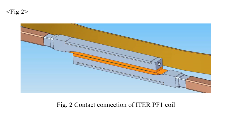
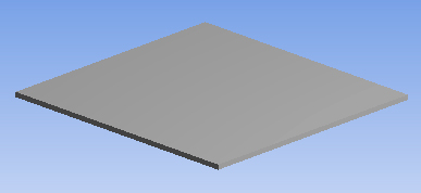
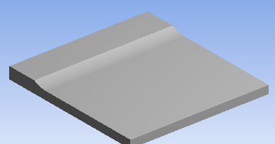
The main feature of the contacts design developed by the specialists of ITER is that the base plate out of stainless steel AISI 316L has got a transitional radius surface R=200 mm. The cladding layer out of copper ASTM B152-C10100, thickness 18 mm, shall fill a radius concave and then shall be welded without discontinuity totally across the entire surface of the base plate. Further machining of the cladding layer allows providing of the required geometry dimensions of the contact connection. Weld quality throughout the entire plane and radius zone should provide the required electrical and mechanical loads at operating temperature of the contact 4˚К. The size of a blank is ((61 to 73) + 18) * 900 * 900 mm. Geometric model of the parts to be welded is presented in Fig. 3. The model includes welding parts with their geometric dimensions, their mutual location, and the distance between them.

Mathematical modeling with ANSYS software [1] ,[2] was applied for optimization of weld process. The geometric model used as basis of calculation had to help with selection and prove the correctness of the selected charge configuration and size, location and configuration of a detonation source, shape and relative positioning of the parts welded. Besides, the weld process has to take place at no tensions close to the limited ones, both in base and cladding plates, in order to eliminate rupture of the blank.
Preliminary conclusions
There were totally 12 experiments planned and consequently 12 sets of plates were prepared for welding.
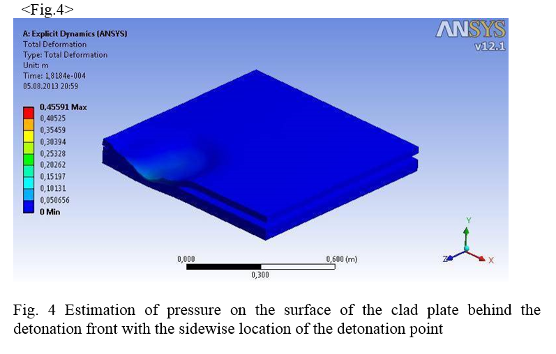
Two preliminary experiments that were performed with the plates having width equal to half of the actual one and aimed to evaluate the future work showed that the detonation point, particularly when located near the edges, leads to asymmetrical contact between the cladding layer and base plate and consequently to incomplete fusion. That is why the point of detonation has not been considered in our further calculations any more, and has not been applied in practice, however, the received estimations of pressure and maximum permissible stresses in the base and cladding plates were taken as the basis for the future calculations.
Calculation and analysis of dynamic behavior of the objects welded
Calculation of the clad front movement, which would provide a homogeneous formation of welding zone, requires a special organization of shock wave front movement along the surface of the copper plate. Explosive layer and geometry of initiators layout above the plate surface is conventionally shown in Fig. 5. When initiating an explosion at the height h above the surface of the plate, the zone of expanding of shock wave in the explosive environment (see Fig. 5 with parallelepiped above the surface of the plate) can be represented as ellipsoid with the centre at the point of initiation. The main axis of ellipsoid is defined by velocity of detonation V1 (~ 8000 m/s) in the initiating cord charge and two other axes are defined by velocity V2 (~ 2000 m/s) in the base charge.

Inside ellipsoid by the time t, pressure is equal to pressure of detonation P0 behind the shock wave front, and outside ellipsoid it is equal to atmospheric pressure. Position of the front in space and time is defined by the equation (1):

On the surface of the plate the front is expanding at the constant coordinate z=0. Thus, the front will come to a random point A on the surface of the plate at the moment defined by the equation (2):

Accordingly, configuration of the shock wave front can be calculated for any time point. The calculated according to the formula (2) field of coordinates and times of the shock wave front position was taken as a boundary condition for solution of equations of the entire system movement in all variants of calculation. The same formula can be used for calculation of spherical and disk-like front.
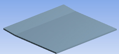
In order to calculate the dynamic behavior of plates under impact it is necessary to evaluate the dynamic performance of the plates, especially the natural frequencies and oscillation modes. The results of calculations for the flat copper plate -1, curved copper plate -2 and the steel base plate -3 are shown in Table 1.
TABLE 1
Design oscillation modes generated in the welded parts at the initial moment of blast effect
 Upper plate straight |
 Upper plate curved |
 Lower steel plate |
 330 Hz (0.003 sec) |
 330 Hz (0.003 sec) |
 430 Hz (0.002 sec) |
 1000 Hz (0.001 sec) |
 1000 Hz (0.001 sec) |
 1100 Hz (0.001 sec) |
 3000 Hz (0.0003 sec) |
 3000 Hz (0.0003 sec) |
 3100 Hz (0.0003 sec) |
Whereas the process typical time (the time of shock wave travel along the surface of the plate) is ~0.0005 s, then significant influence on formation of clad front can be provided only by natural waves with frequencies of ~3000 Hz and higher. Besides, the more rigid the plate, the more simple shape of the wave is at the same frequency. Thus, 5 bend of the upper plate increased its rigidity in the transverse direction relatively to the main direction of clad front movement. Modes of natural oscillations can significantly influence on weld quality, and the problem of absorbing of these modes represents the issue of the day.
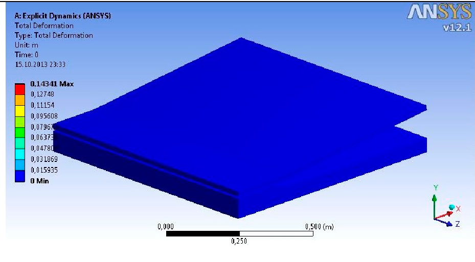
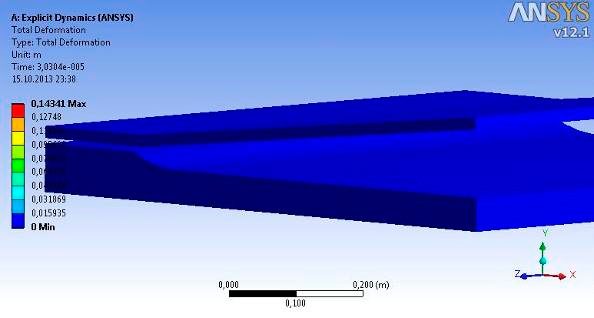
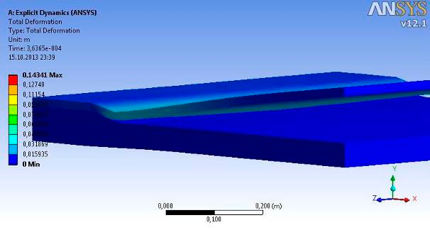
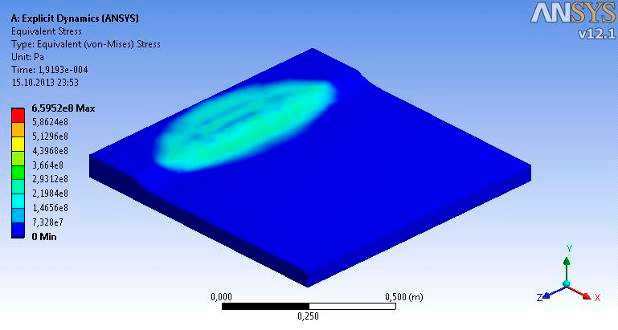
In order to calculate the contact interaction of plates during shock contact we used a dynamic calculation module ANSYS 12.1 in the form of an explicit solution of the equations of motion (Explicit Dynamics). The quality of the weld process was forecasted and evaluated considering the shape of the cladding front and by maximum contact stresses behind the cladding front. The best proportion of detonation pressure P0 behind the shock wave front to strength of materials welded (conventional yield strength) was received in the range of 0.25-0.5. Besides, it provides enough pressure in the area of welding, and materials do not receive excessive deformations. The stages of cladding process are shown in a way of camera single-shot recording in Table 2, Table 3, and Table 4.
The calculation scheme used shows position of the plates in their original status with a zone of generating of initial impact impulse (Fig. 6).
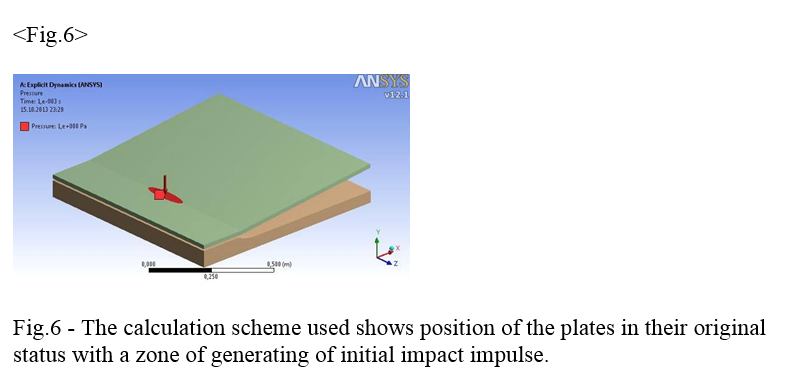
TABLE 2
Stages of cladding process in a way of camera single-shot recording, showing a good homogeneity of a cladding front movement by time and direction.
Expansion of moving zone
 |
 |
 |
 |
 |
 |
 |
 |
TABLE 3
Stages of cladding process in a way of camera single-shot recording, showing a good homogeneity of a cladding front movement by time and direction
Expansion of moving zone from a different visual angle
 |
 |
 |
 |
 |
 |
 |
 |
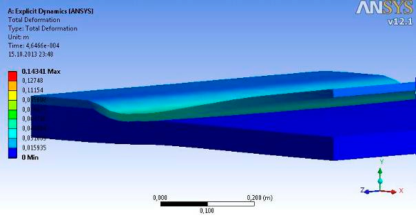
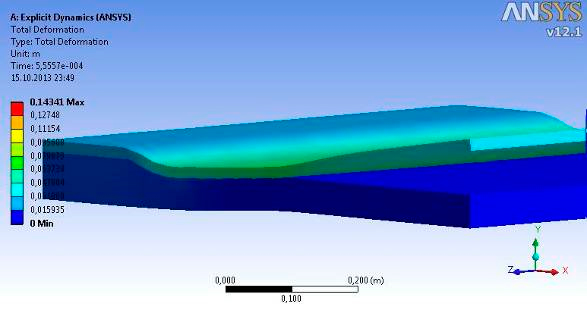
TABLE 4
Stages of cladding process in a way of camera single-shot recording, showing a good homogeneity of a cladding front movement by time and direction.
Expansion of contact stresses and equivalent stresses along the bottom plate
 |
 |
 Start of generation of advancing deformation wave |
 Moving of cladding front along the upper platform |
 |
 |
 Moving of cladding front along the lower platform |
 |
 |
 |
 |
 |
 Generation of zones of possible separation of layers on edges of the clad plate |
 In the central area of the clad plate there is a zone of a steady-state contact which provides the proper welding |
 |
Cladding of the upper plate runs not from horizontal position, and lateral rigidity of the plates affects positively, cladding front is almost straight. Stress zone is almost homogeneous in transverse direction towards the moving front.
Realization and practical optimization
Methods of influence on common dynamics of components in a package for welding could be realized in practice by a few ways. The variants could be as follows:
- Location of detonation point of explosive and shape of detonation shock wave.
- Geometry and size of the charge.
- Form of cladding layer and its position relatively towards the base plate.
- Connected rigid support of the base plate (its size and mass).
The final layout of components of a package for welding is shown on Fig. 7.
It should be noted that each planned experience was prelimenary well thought in order to avoid serious mistakes. Thus, in reality, experiments and calculations were alternated with each other, and after each experiment a correction was performed and a method to eliminate disadvantage was found.
Every planned experiment was preliminarily calculated to exclude rough error.
First we tested influence of detonation line position relatively to the rib of the upper platform of the base plate - the plane AB, and charge thickness BC. However, in all cases, the nature of welding looked almost similar – the planes and the radius zone were bonded except two areas on the lower platform of the base plate located directly after the end of the curved part in the edge area (of rounded shape, with conventional diameter about 50-60 mm). Material of a cladding layer in these zones is of a convex shape, and the counter surfaces of the base plate and the cladding layer have traces of contact interaction (generation of wave) - see Fig. 8 and Fig.9.

The detailed simultaneous analysis of the performed calculations and results of the experiments let us suppose that advancing impact of the cladding plate along the upper platform of the base plate causes its elastic bending with edges bent downward and its middle part bent upward (the first mode). Almost at the same time, contacting and welding is already starting along the surface of the radius zone and along the beginning of the flat zone of the lower platform of the base plate. By the next moment, the shape of base plate deformation is changed to the opposite, besides, in the most weaken edge zone of the welded item we see destruction of the weld joint and stretched zone of the cladding layer bending upwards. When the probable reasons of nonbonding were found out, we settled the task to find a technological method to keep the acting factors to a minimum.
Approximate balance was found by changing the size and shape of the charge on the top platform of the base plate and by adding some additional hard solid basement below the base plate such as a cast concrete slab. The combination of these techniques have reduced the zone of discontinuities, but not eliminated them completely.
As soon as the quality of the weld on the upper platform of the base plate has no practical importance, in the next step of optimization we reduced that part of the charge located above the upper platform of the base plate. However, in case of a significant reduction of the charge, excessively strong deformation took place in the middle part of the plate – with bend downwards. Therefore, further on, an approximate balance by the charge size was restored above the upper platform, as some "average value". In addition, a rigid solid base (a concrete slab) was installed under the base plate. Combination of the mentioned methods let us reduce zones of discontinuities, but not eliminated them completely.
As soon as all possible practical ways to influence on dynamic properties of the base plate were worked over in the 5th and 6th experiments, it was decided that we should perform next two experiments as follows: in the seventh experiment we made an attempt to solve this problem simply by force action on area with discontinuities, just by covering this part of cladding layer with a strip of pure explosive; in the eighth experiment we changed geometry of the cladding layer by bending a part of it 5˚ upwards from the line AB. An additional force applied to the zone of discontinuities did not bring any positive effects, however the planned changing of geometry of the cladding layer, combined with optimization of the charge form and using of a rigid base for the base plate resulted in long-awaited success. However, it should be noted that the combination of the oscillation modes and accompanying this process loads lead to distortions in the shape of contact surface in the form of variations in the amplitude of the wave at the interface of metals.
The solution was successfully obtained in the 8th experiment by a correct tailoring of all related factors. The result was further optimized, and used to foresee the specific nature of joining of the parts. The obtained results are shown in Fig.11 and Fig. 12.
Conclusions
The performed work shows the extraordinary importance of considering dynamic interaction of the parts welded as macro-objects, that let us find the solution for a nontrivial task, and showed that it is also possible to improve welding of usual flat work-pieces. Besides, it clearly demonstrated the need to develop models of mechanical (dynamic) joining (welding) of the contacting surfaces of bodies in condition of plastic flow of materials at relatively low preheating.
Correspondence address: AO ENERGOMETALL, 195220 SAINT-PETERSBURG, RUSSIAN FEDERATION, UL.GZHATSKAYA 21/2, This e-mail address is being protected from spambots. You need JavaScript enabled to view it , VLADIMIR VAKIN